Line Attribute Styles
In the Project Environment dialog, in [project] > Document Production > Line Attribute Styles, the Line Attribute Style configuration objects define how the edges, the hidden lines, and the centerlines of 3D objects are visualized in drawing views. These settings are not applied to 2D drafting objects or annotations.
You can create a separate line attribute style for each drawing type that has specific requirements. For example, you might want to completely remove hidden lines from general layouts but display them as dashed lines in equipment layout drawings and as dotted lines in support drawings.
Also the Layer Style configuration objects are managed via line attribute styles.
In the document editor, the designer can select the line attribute style and the layer style to use in specific views, as described in Select line attribute style.
Defining a line attribute style
You can create a new line attribute style as described below.
Do the following:
-
In Plant Modeller, select File > Environment > All library and project.
-
In the Project Environment dialog, browse to [project] > Document Production > Line Attribute Styles.
-
Select New > Line Attribute Style. The Editing Line Attribute Style dialog opens.
-
Define the general properties:
-
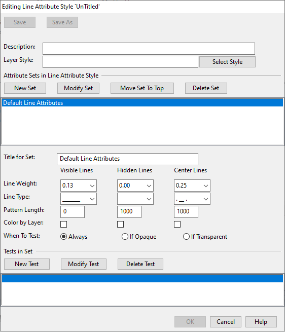
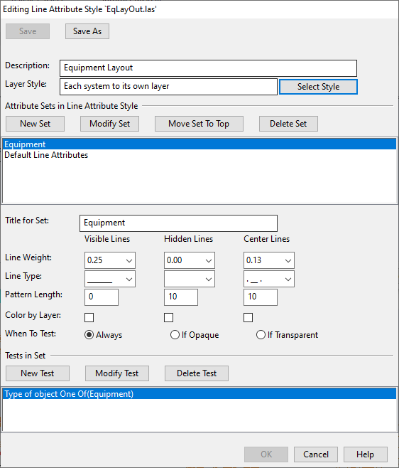
Description – Enter a description for the style. (The name of the style you will define when you save the style.)
-
Layer Style – Click Select Style to select the layer to use if line weight, line type or line color is set to be adopted from the layer.
For more information on layer styles, see Defining a layer style.
-
-
Attribute Sets in Line Attribute Style – This section defines the attribute sets to use. An attribute set allows the objects that a given set defines to be drawn in a specific style, so that they can be easily differentiated from the other objects in the view.
The default set, "Default Line Attributes", should always be the last set in the list, so that it can be applied to any lines that do not get their style from any other set.
To create a new attribute set, do the following:
 Show/hide details
-
Title for Set – Enter a name for the attribute set to create and click New Set.
-
Line Weight – Select a line weight for visible lines, hidden lines, and centerlines.
If the line should not be drawn at all, set the value to 0.00.
-
Line Type – Select a line type for visible lines, hidden lines, and centerlines.
If the line should not be drawn at all, select the empty type.
-
Pattern Length – Select a pattern length for visible lines, hidden lines, and centerlines whose line type is a dotted, dashed, or dash-dotted line.
For solid lines, set the value to 0.
-
Color by Layer – Select this option if you want the line color to be taken from the layer that is selected in the layer style configuration—see Defining a layer style. If not selected, the line color is taken from the color style settings of the drawing view—see Color Style.
-
When to Test
-
Always – Hidden lines and centerlines are always shown unless the line type prevents the line from being drawn.
-
If Opaque – Centerlines are shown only when the object is set to be transparent.
-
If Transparent – Hidden lines are shown only when the object is set to be transparent.
-
-
Tests in Set – To specify what kind of objects to include in the set, click New Test and define an object selection test. For more information on selection tests, see Query test editor.
-
Click Modify Set to accept the set.
-
-
If you want to rearrange the set list, click Move Set To Top to move the currently selected item to the top of the list. Continue moving items to the top until the items are in the desired order. Just remember to leave the default set at the bottom of the list.
-
To save the line attribute style in the project database, click Save, enter a name for the style and click OK.
-
Click Save As if you want to create a copy of the current style and save it with another name.
-
Click OK to close the line attribute style editor.
Modifying a line attribute style
You can modify an existing line attribute style as described below.
Do the following:
-
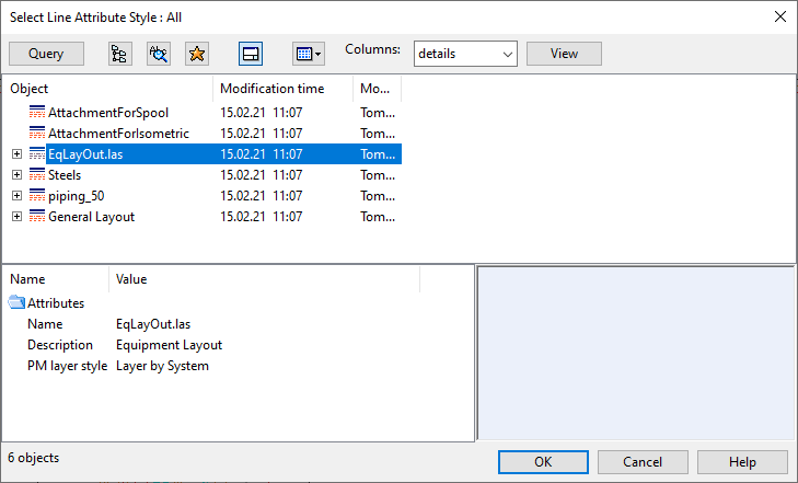
In an open Plant Modeller document, right-click the view and select Views > Select Line Attribute Style. The Select Line Attribute Style dialog opens.
-
Right-click the line attribute style to edit and select Edit. The Editing Line Attribute Style dialog opens.
-
You can edit the style's description or assign a different layer set to the style. For more information on layer styles, see Defining a layer style.
-
You can manage the attribute sets of the line attribute style:
-
To add a new attribute set to the line attribute style, enter a title for the set and click New Set.
-
To edit a line attribute set, select the set and change its title, properties, or selection tests as appropriate, and then click Modify Set to accept the changes.
-
To change the order of the sets in the list, click Move Set To Top to move the currently selected item to the top of the list. Continue moving items to the top until the items are in the desired order. Just remember to leave the default set at the bottom of the list.
-
To delete a line attribute set, select the set and click Delete Set.
-
-
You can manage the selection tests of an attribute set:
- To add a new selection test, click New Test. For more information on selection tests, see Query test editor.
- To modify a selection test, select the test and click Modify Test.
- To remove a selection test, select the test and click Delete Test.
-
Click Save and then Close.
Defining a layer style
A "Layer Style" configuration object defines rules that allow 3D objects to be assigned to specific layers when a Plant Modeller drawing is exported. These settings are not applied to 2D drafting objects or annotations, their layer usage is defined in annotation properties—see Annotation Properties.
Layer style is a property of a line attribute style. Administrator must create at least one layer style that can be linked to any number of line attribute styles. Accordingly, when a designer selects which line attribute style to use in a drawing view, the choice also determines the layer style for that drawing view.
Prerequisites
-
You have created the layers that the layer style is to use, as described in Layer configuration.
Do the following:
-
In Plant Modeller, select File > Environment > All library and project.
-
In the Project Environment dialog, browse to [project] > Document Production > Line Attribute Styles.
-
Right-click the line attribute style where you want the layer style to be used and select Edit. The Editing Line Attribute Style dialog opens.
-
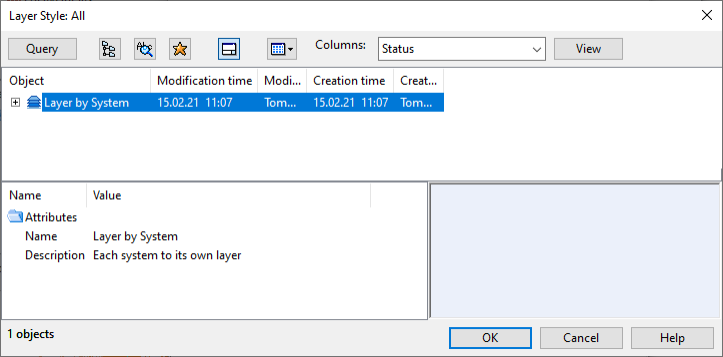
Click Select Style. The Layer Style dialog opens, listing all the layer styles.
-
Right-click the list pane of the dialog and select New > Layer Style. The Editing Layer Style dialog opens.
-
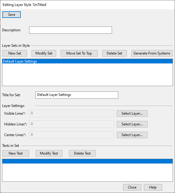
Description – Enter a description for the style. (The name of the style you will define when you save the style.)
-
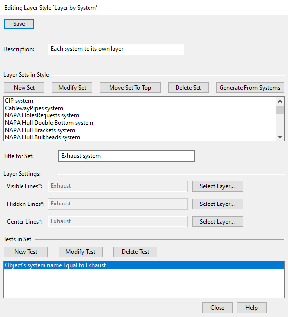
Layer Sets in Style – This section defines the layer sets to use. A layer set allows the visible lines, hidden lines, and centerlines of the objects in the set to be assigned to the same layer or different layers. You can generate a layer set per system definition or create the required layer sets manually, as appropriate.
The default set, "Default Layer Settings", should always be the last set in the list so that it can be applied to any objects that do not get their layer assignment from any other set.
-
To generate a layer set for each system, so that objects that belong to the same system are assigned to the same layer, click Generate From Systems. A dialog opens for approving the action. If there is an existing layer whose name matches the name of a system, then that layer is used instead of generating a new one.
-
To create a custom layer set, do the following:
Show/hide details
-
Title for Set – Enter a name for the layer set to create and click New Set.
-
Visible Lines – Click Select Layer and select the layer to which to assign visible lines.
- Hidden Lines – Click Select Layer and select the layer to which to assign hidden lines.
- Center Lines – Click Select Layer and select the layer to which to assign centerlines.
-
Tests in Set – To specify what kind of objects to include in the set, click New Test and define an object selection test. For more information on selection tests, see Query test editor.
-
Click Modify Set to accept the set.
-
-
-
To change the order of the sets in the list, click Move Set To Top to move the currently selected item to the top of the list. Continue moving items to the top until the items are in the desired order. Just remember to leave the default set at the bottom of the list.
-
To save the layer style in the project database, click Save, enter a name for the style, and click OK.
-
Click OK to close the layer style editor.
Modifying a layer style
You can modify an existing layer style as described below.
Do the following:
-
In Plant Modeller, select File > Environment > All library and project.
-
In the Project Environment dialog, browse to [project] > Document Production > Line Attribute Styles.
-
Right-click any line attribute style and select Edit. The Editing Line Attribute Style dialog opens.
-
Click Select Style. The Layer Style dialog opens, listing all the layer styles.
-
Right-click the layer style to edit and select Edit from the context menu. The Editing Layer Style dialog opens.
-
You can edit the description of the layer style.
-
You can manage the layer sets of the layer style:
-
To add a new layer set, enter a title for the set and click New Set.
-
To edit a layer set, select the set and change its title, layer assignments, or selection tests as appropriate, and then click Modify Set to accept the changes.
-
To change the order of the sets in the list, click Move Set To Top to move the currently selected item to the top of the list. Continue moving items to the top until the items are in the desired order. Just remember to leave the default set at the bottom of the list.
-
To delete a layer set, select the set and click Delete Set.
-
-
You can manage the selections tests of a layer set:
- To add a new selection test, click New Test. For more information on selection tests, see Query test editor.
- To modify a selection test, select the test and click Modify Test.
- To remove a selection test, select the test and click Delete Test.
-
Click Save and then Close.
-
Click OK to close the Layer Style dialog.
-
Click Cancel to close the Editing Line Attribute Style dialog.